These machines were developed long before the days of digital cameras so the quality of some of the pictures are not the best. Our business was manufacturing and photography was rarely more than a passing fancy.
The mills were developed in conjunction with the company that owned and operated them. They were supposed to take the machines to market but never did so.
The basis of our design was an electronic load-sharing system that I had learned from a magazine article describing the work of a company in California. The design was not patented as it was really just a mathematical proof of a special operational amplifier.
I applied it to rolling mill that traditionally suffered from problems of speed mismatch because each roll was a different shape and size and therefore ran at a different linear speed. The essence of my design was to load equalise the sixteen motors so that each ran at a speed to match the actual diameter of its particular roll. The system worked well, so well in fact, that the mills were regularly operated much beyond their design specification and then suffered from problems caused by saturating motor controllers.
The owners never got to grips with this problem and could not be persuaded that the mills were simply being abused.
The very first Rolling Mill
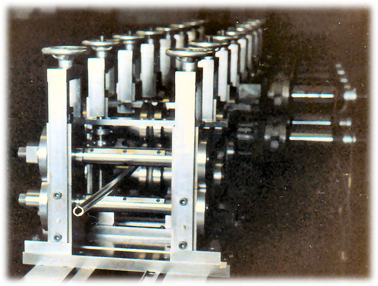
This is the very first picture taken of a rolling mill and shows the first mill forming stage producing the very first test piece. The 16mm diameter tube can be seen heading towards the camera. This was the culmination of a year's work.
The mills were designed by myself with a lot of guidance from the manager of the customer's workshop. The project started around 1979 and terminated around 1986.
The mill stands above are driven by fairly small electric motors and gearboxes. The motors were adequate to the task but the gearboxes contained a plastic gear in the early stages which soon showed its vulnerability. By this time we had developed our own gearcutting ability and soon replaced the plastic gears with steel ones. Subsequent mills were driven by a house designed gearbox which never gave a moments problem again.
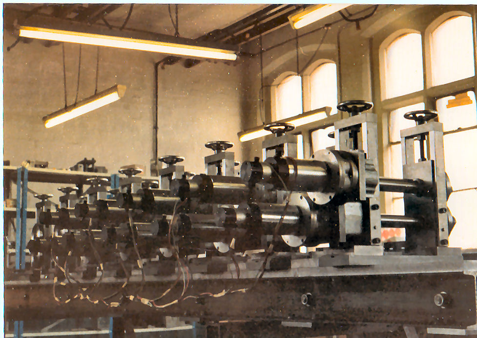
Another view of the first mill on test.
Thyristor Drive Unit for the first mill.
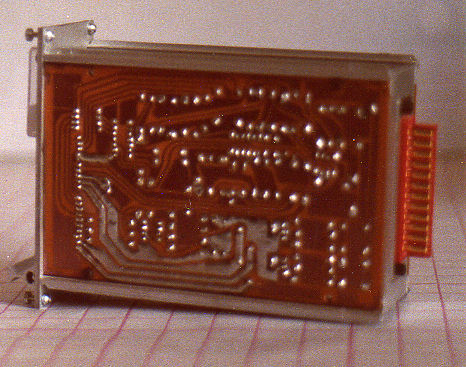
This unit was designed and built in house, even down to the printed circuit boards. Subsequent designs were produced completely in-house except for the printed circuit boards which were designed and developed in house but the pcb's were sub-contracted. The boards were loaded by wives and children of the directors who became accomplished electronics build technicians. A total of around 90 such units were built over six years together with much other control equipment. It was all designed and built in house.
Hot Swappable Thyristor drive unit
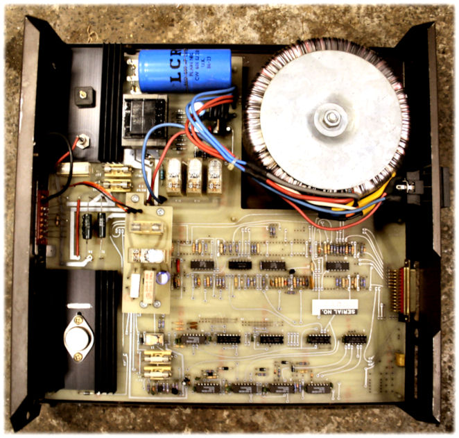
This was the final form of controller which was hot swappable and drove a half horsepower dc motor at up to 180 volts. Any one of the sixteen drive units could be removed and replaced and would automatically assume the correct driving conditions for the motor, stand and forming roll load and speed which was required.
(Most of ) The complete Mill
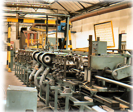
Virtually every piece of this mill was designed and produced in house. In the foreground is the traveling saw which automatically cuts the tube into lengths of around 6 metres.
The decoiling mandrel
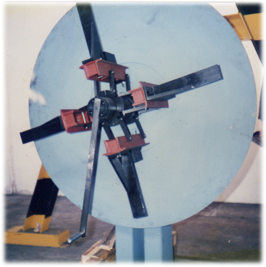
This is where the prepared steel coil starts its journey
Tube forming stages
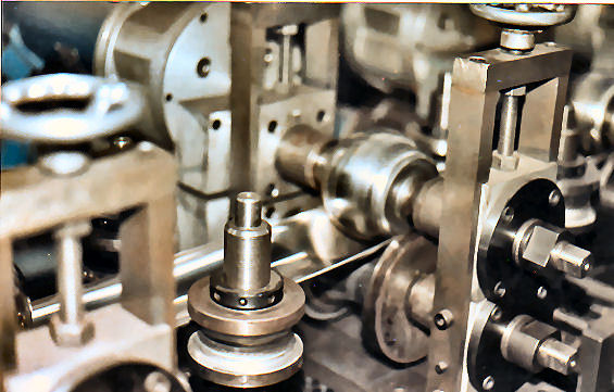
Here the steel strip can be seen between the forming rolls that take strip steel in at one end and send formed tube out at the other.
First four Forming Rolls
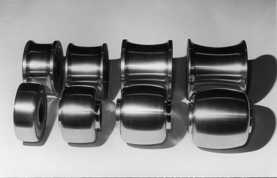
We spent a lot of time leaning how to make the precise forms needed using our new CNC lathe which could cut any shape that can be computed - if you know what shape you want. Before CNC machines, producing these rolls was a very highly skilled job. Even with them it was a very satisfying task.
The welding operation
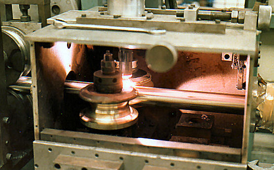
Here the tube is leaving the forming section and being held within the weld box by two phosphor bronze rolls to conduct the arc welding current. The weld arc can be seen but is normally covered by a plate which retains the inert atmosphere maintained within the box by the continuous insertion of nitrogen. The weld power source was commercial but all other items were designed and manufactured in house.
Sizing and straightening section
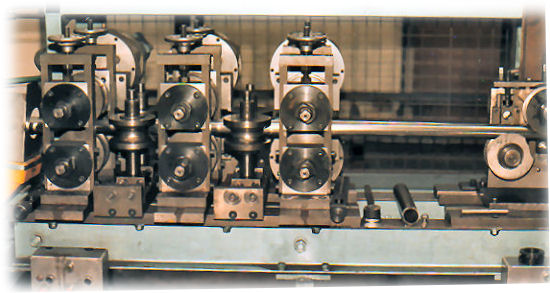
After welding the tube is squeezed to slightly reduce its size and make it round to fairly close tolerances. One day I was called to see a mill that would not work. I checked everything I could and found no problems but the mill would simply not run. Eventually, out of desperation, I checked the size of the tube they were making and found it to be much too big. They checked their figures and we found that the machine was trying to produce 38 mm tube using strip intended for 41 mm tube. The machine had been reducing this tube, nearly 3 mm oversize, to the correct size for three days before it finally gave up in protest. The extra load imposed by this error was, I calculated about five times the designed load and the mill had carried it for three days without protest. The customer was still not impressed.
The digital saw control system
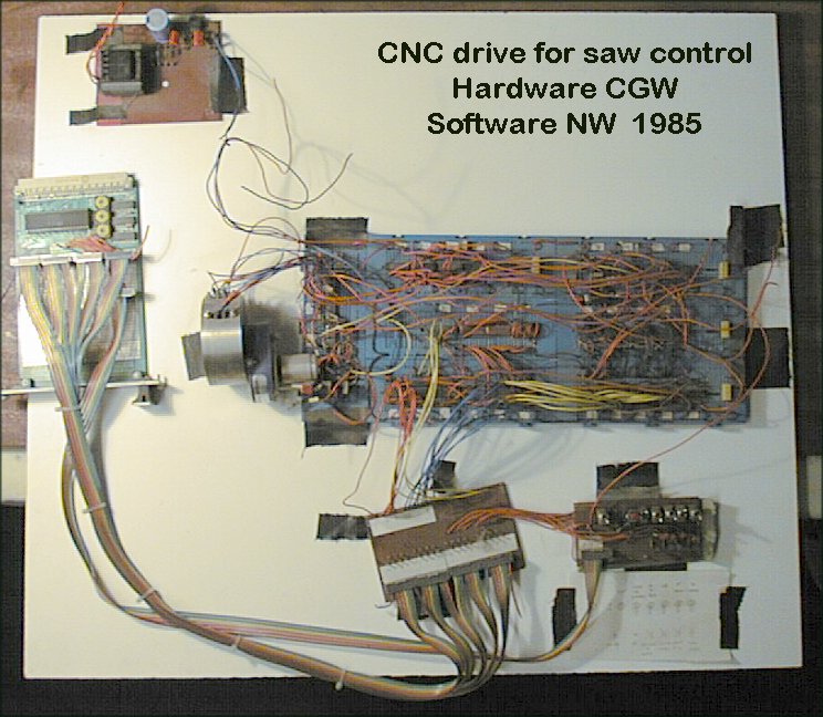
Control of the saw was an exercise in digital logic which was undertaken at first by simple "and" and "or" gates and switches. This project to make it fully controlled was undertaken in house and the software written by Nick Walker as his fourth year university project.
Mill gearbox designed in house
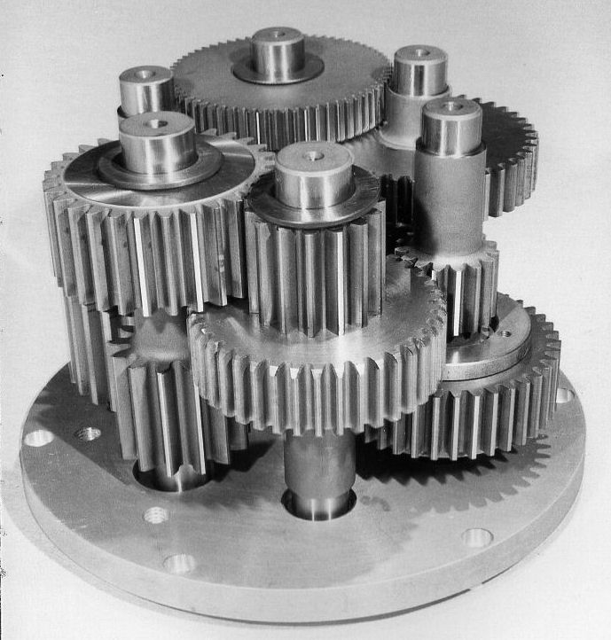
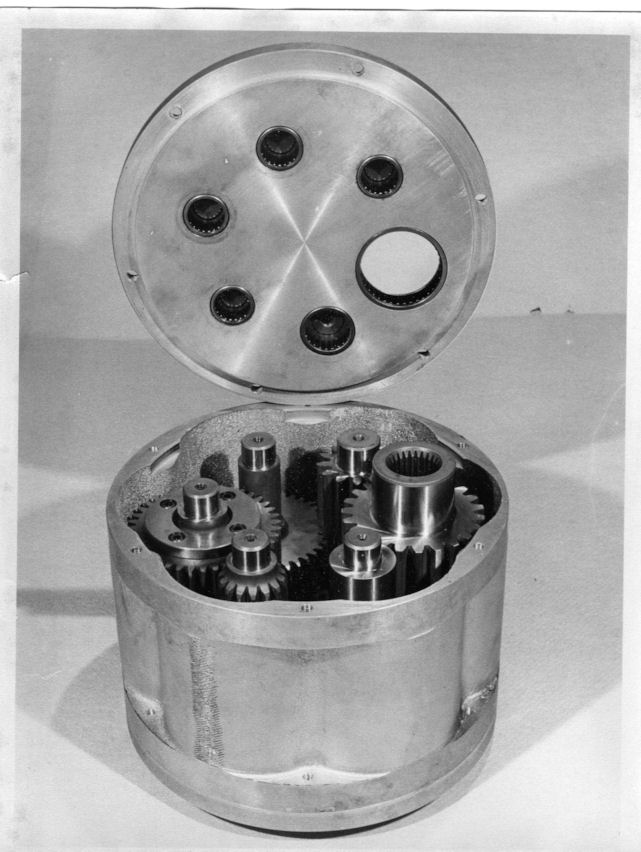
The first mill made tube up to fifty percent bigger than the specified design parameters and the demand for larger tubes continued apace. The second mill was designed with a much larger gearbox and motor to push the design parameters much further out. These gearboxes were totally designed and produced in house. About seventy gearboxes were produced and gave over five years service with never a single maintenance action required.
Colin Walker 2012